
DMA (Direct Memory Access)
The Comprehensive Guide to Data Throughput Mastery

Outline
Intro
Why DMA
Common DMA Configurations/Layouts
Customizations and Specializations
Software Design
Maximizing Performance Potential
As always, start with the Schematic:
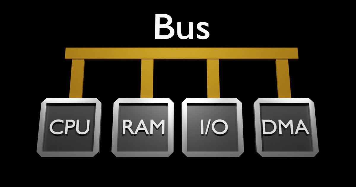
                 CPU: Central Processing Unit (Where your code is executed)
                 RAM: Volatile Memory for storing data.
                 I/O: Input/Output Peripheral, this could be a Simple UART/Ethernet/Etc...
                 DMA: Direct Memory Access Hardware
DMA, an abbreviation for Direct Memory Access, stands as probably the most obtuse Acronym as you'll find in embedded engineering.
Fundamentally, the DMA is hardware specialized for moving data. Consequently, the term DMA occasionally used interchangeably with 'data movement'.
Why DMA?
Consider a contrived scenario, where the CPU actively polls hardware, such as RS232 or UART, to transfer data:
void write_to_hardware(const uint8_t * source, uint8_t bytes_to_write) {
    for (uint16_t i = 0; i < bytes_to_read; ++i) {
        while (hardware_is_not_ready()) { nop(); }    // STEP 1
        uint8_t data = source[i];                     // STEP 2
        hardware_write(data);                         // STEP 3
    }
}

//... somewhere in the main loop
write_to_hardware(source, bytes_to_write); // Blocked until complete
//... Ok to do more calculations
Visual Steps:
Polling I/O Readiness [hardware_is_not_ready()]
Issuing Reading IO Register
Reading Response
Fetching data from RAM to CPU: [uint8_t data = source[i]]
Issuing Read to RAM
Reading Response
writing hardware: [hardware_write(data)]
Writing Data to IO
This process showcases significant bus activity and CPU cycles spent on polling I/O readiness and managing data transfer.
Remember, the CPU's resources are the most precious resource in most systems.
Thus the DMA was created to offload this mundane task, and gain the possibility for more performance and efficiency.
The Same Task concurrently
Same scenario, but the DMA is configured to execute the same task concurrently, triggered solely by the CPU.
While this approach requires additional setup and requires managing DMA completion, it substantially offloads the CPU.
void write_to_hardware_via_dma(const uint8_t * source, uint8_t bytes_to_write) {
    configure_dma_source(source);
    configure_dma_length(bytes_to_write);
    dma_trigger();
}

// init
setup_dma_target();

//... somewhere in the main loop
write_to_hardware_via_dma(source, bytes_to_write);
// ... CPU does more complex pertinent.
// Manage via Flag/ISR completion of DMA
Similar Video, but with a side channel from IO to DMA.
Visual Steps:
Configure DMA Static Settings, like Target (IO in this case) [setup_dma_target()]
Configure the DMA with the Memory to Read From, and how much to write, Then start transaction.
configure_dma_*
dma_trigger()
Managing DMA Transfer Completion.
What you'll notice here, is most of the Bus activity is driven by the DMA. It behaves as a Bus Master, similar to the CPU. Multitasking the system, has freed the CPU to do something else, while the DMA does the copying. However, doing this has changed our 'simple' system model, as now we have to Masters (CPU and DMA) contending for the System Bus. To resolve this contention, Bus Priorities are established, typically the CPU has the highest priority by default.
Additional mechanisms are put in place to prevent CPU stalls waiting for the System Bus.
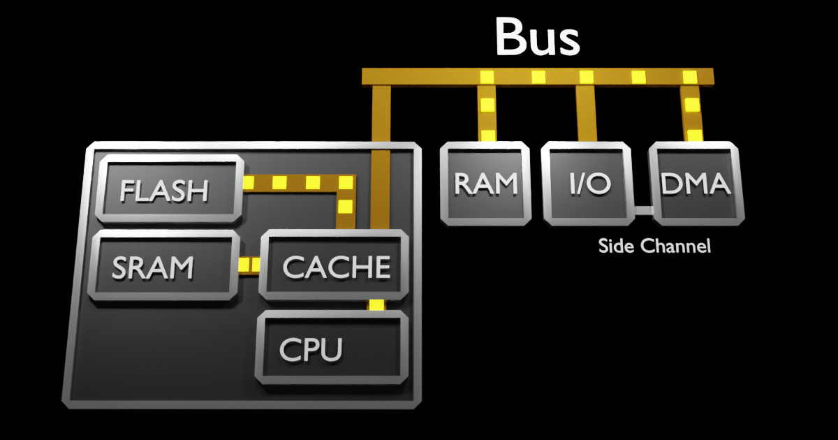
These are mainly CPU Data/Instruction Cache, and SRAM/Flash accessible via a local CPU-only bus. Usually, your interrupts routines and other time sensitive Data/Functions are located in these regions. The advent of DMA capabilities prompted hardware designers to widely incorporate them throughout systems. However, before delving into these variations, let's discuss more of the DMA's functionalities.
Deeper
Inside any 'DMA' are channels (sometimes called streams). Each Channel behaves like the 'DMA' in the above examples. Each channel has it's own priority, and can be configured typically in one of these setups:
Peripheral-to-Memory, Memory-to-Peripheral, or Memory-to-Memory.
Again with the Acronym, the DMA, is now a 'DMA Module', however referenced as 'DMA' only.
Some times the channels priority is software configurable. Most times it's priority is based on its channel order.
In some Microprocessors, only certain channels have specific IO Side Channels connected (saving silicon), where as other as high configurable.
Common DMA Configurations/Layouts
Bus Address Mode/Alignment, typically 1/2/4/8 bytes:
Every System Bus is different, however your data's address alignment must be accounted for.
There are restrictions when connecting to a Peripheral (Read your Manual).
Some require 8 bit transfers (Like UART), because the target register is only 8 bits.
FIFO Buffers:
When manipulating data, the DMA's FIFO will be filled as a buffer between it's source/destination.
Some channels share the same FIFO buffer.
Transfer size:
Don't be fooled here, this is generally size is in 'units' based on how you configured it's Address Format (1/2/4/8 bytes).
Beats/Blocks/Burst Size
This is the length of data the DMA will 'lock' the Bus, blocking other masters from accessing the bus.
It is considered uninterruptible, and you should be aware of it in time sensitive applications.
Outside of that, it should match what the Peripheral is expecting. IE, burst of 1 for a 1Byte UART Tx Register. However, if the UART has a Buffer, then the burst should match the Buffer. IE, burst of 8 for a UART with a FIFO of 8.
Notes on Address Space
Typically, the DMA has access to the whole Bus that it is attached to. Remember that the Bus Address may not be the same for your CPU (IE, some PowerPCs have a ‘36 bit bus’, whereas the DMA would only be able to access 0x0000_0000 to 0xFFFF_FFFF.
Customizations and Specializations
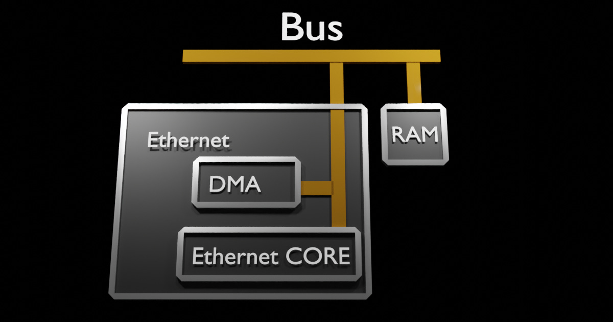
As DMA hardware design is well understood, hardware designers place them wherever they can to accelerate the potential for total system data throughput. This means read your Reference Manual, it most likely will have more than just the generic DMA above. It may have MDMA, BDMA, DMAs with CRC calculations; Most high throughput Peripherals, like Ethernet, have DMAs are embedded into the Peripheral. See Below.
Let's talk design
Typically, in any robust system. The programmer will configure each channel based on the Peripheral they want to Offload. This assures allocation of those resources, avoiding runtime errors. The remainder of Channels should be configured as Memory-to-Memory.
While it is tempting to swap out memcpy/memset with these new Memory-to-Memory channels, you aren't the first with those thoughts. You should understand that the DMA may run from a slower clock, and the other overhead/headaches of flushing cache (I'm looking at you STM32F).
Always Time this, and understand that using a DMA may not be the optimal solution.
Maximizing Performance Potential
With great Power comes great responsibilities.
Countless Hardware Engineering careers have focused on achieving maximum system potential. As an Embedded Software Engineer, it's your responsibility to pursue this objective relentlessly. Given that, for most systems the complexity had increased exponentially, placing more pressure on the Software Engineer.
It's important to document what is accessing the System Bus, and each non-trivial Sub System Sub for that matter. Without even the simplest documentation, it's hard to reason system performance and achieve the goal of maximizing the system.
Good luck, and always flush the cache.